Innovative single and three-phase power supply design

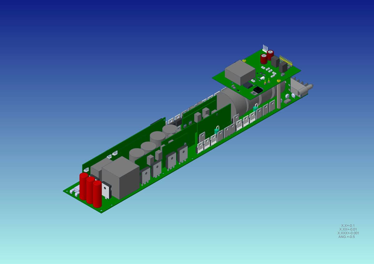
Elenos is among the few in this industry to have a dedicated department for the design of switching power supplies. We recently designed a new supply to power a future ultra-compact solid state broadcast amplifier, for either FM or TV, with either air or liquid cooling.
The power supply is highly specialized and is integrated into the modular amplifier. The controller is based on a high performance dual core microprocessor from Texas Instruments which is specifically designed for industrial power electronics applications, as well as digitally managing the power supply. the RF section and communications with the outside world via CAN bus.
The new power supply can be connected to three-phase or single-phase mains providing the same nominal power of 1.6kW output. The power factor corrected input stage is a three level Vienna rectifier, modified with the addition of a fourth branch, which operates with 3 branches for the three-phase input, and with 2+2 in parallel for the single-phase input.
To overcome the problems related to having a single universal power supply for different markets, it was decided to divide the electrical distribution networks into two groups and therefore, to design two versions of the power supply by changing only the input stage magnetic components and some power components and the turns ratio of the transformer of the LLC DC/DC converter stage, keeping all the rest of the circuitry unchanged.
In the case of a single phase version, the wide range of the AC input voltages required would have involved the design of the power section, the network interface, the power factor corrector (PFC), both the DC / DC converter, through the semiconductor devices and magnetic components capable of withstanding both high currents (at low mains voltages) and at the same time high voltages. The magnetic components are those that would have suffered the most, in particular the inductors of the PFC and the transformer of the DC / DC resonant stage.
The losses would increase excessively at low mains voltages and the stress on the power electronic devices at high mains voltages, with the consequent need to oversize both active devices, as well as the magnetic components. The latter in particular would have increased in physical dimensions in contrast to the limitations imposed by the mechanism of the drawer and by the small spaces available.
In the end, in order to obtain optimum efficiency, the transformer is designed to change the transformation ratio depending on the input voltage range.
Now, the two planned versions are:
For European networks with the following input specifications:
- Three-phase 400Vac -25% / +20% (300Vac to 480Vac), 47 to 63 Hz.
✓ Rated power 1.6kW (power derating below 300Vac).
✓ Overvoltage input: 487Vac (the power supply is turned off with automatic reset).
✓ Protection for maximum overvoltage: 530Vac rms. - Single-phase 230Vac -25% / +20% (172V to 276V), 47 to 63 Hz.
✓ Rated power 1.6 kW (power derating from 88Vac to 172Vac).
✓ Overvoltage input: 280Vac (The power supply is turned off with automatic reset).
✓ Protection for maximum overvoltage: 300Vac rms.
For American networks with the following specifications:
- Single phase 115Vac -25% / +20% (86Vac to 138Vac), 47 to 63 Hz.
✓ Rated power 1.6kW (power derating below 86Vac).
✓ Overvoltage input: 140VAC (the power supply is turned off with automatic reset).
✓Protection for maximum overvoltage: 150Vac rms. - Two-phase 210Vac -25% / +20% (157Vac to 252Vac), 47 to 63 Hz.
✓ Rated power 1.6kW (power derating below 157Vac).
✓ Overvoltage input: 255Vac (the power supply is turned off with automatic reset).
✓ Protection for maximum overvoltage: 274Vac rms. - Three-phase 210Vac -25% / +20% (157Vac to 252Vac) 47 to 63 Hz.
✓ Rated power 1.6kW (power derating below 157Vac).
✓ Input overvoltage: 255Vac (the power supply is turned off with automatic reset).
✓ Protection for maximum overvoltage: 274Vac rms.
In the PFC stage there is an inrush current limiter capable of withstanding repeated mains failures without failure. The PWM frequency of the PFC is 70KHz. Given the circuit complexity of the PFC circuitry, control is given to the main core of the Texas Instruments TMS320F28377SPZP microprocessor. The main core is more powerful than the secondary core which is used instead for the management of the LLC resonant stage and the modified Vienna rectifier circuit. The demonstrated efficiency is 94%.
The power supply will operate under these conditions:
- Operating temperature range: -20 to +50°C.
- Maximum heatsink temperature: 75°C @ 50° ambient and 80% ventilation.
- Temperature protection: up to 75°C with progressive power derating.
- Storage: -20 to +85°C
- Humidity: up to 95% non-condensing
- Operational altitude: 3,000M
Maximum voltages:
- 2.5KV Vac for 60 seconds from input to ground
- 4KV Vac for 60 seconds from input to output
- 0.5 KV for 60 seconds from output to ground
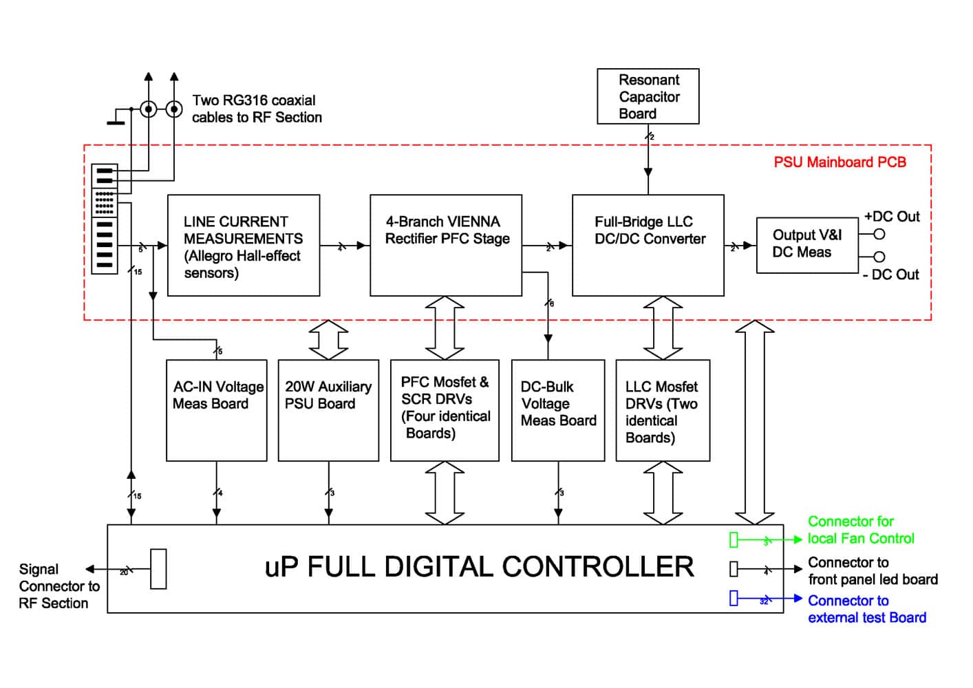
In the block diagram above, the red dashed line represents the power supply motherboard which contains all the power sections, the network interface (PFC) and the DC / DC converter (LLC stage). On this board there are also some circuit sections to accurately measure the input line currents, the measurement of the primary current of the bridge rectifier and filter and for the measurement of DC output voltage and current.
The blocks outside the dotted line represent separate boards for voltage measurement of the input and the DC bus between the PFC and the rectifier/filter, the PFC and LLC power mosfet driver boards, the control logic board, and the 20W auxiliary power supply board which powers the internal circuitry.
But the stage that most of all represents the main innovation of this power supply is the interface to the electrical network, the single-phase / three-phase power factor corrector!
The classic Vienna rectifier consists of three main branches one for each phase, to which we’ve added a fourth identical branch. This fourth branch remains inactive in three-phase three-wire operation and is used as a neutral connection in the case of a three-phase four-wire network.
The innovation is found in the single-phase operation where the four branches of the Vienna Rectifier are connected in parallel two by two on the network connector and two are used for the neutral, two for the phase . In this way the input current is doubled while keeping the stress on magnetic and active devices practically unchanged compared to the three-phase case.
Another difference introduced with respect to the classic Vienna Rectifier configuration is the replacement of diodes in the rectifier bridge with SCRs which are controlled by the control logic when the power supply is turned on create a soft start.
These are innovations which have not been previously implemented in broadcast OEM supplies.
The supply automatically measures voltages and currents on the four terminals of the network connector and recognizes whether it is connected to a three-phase network or to a single-phase network. Then on the basis of this configures itself properly.
The bridge rectifier is configured to automatically switch from a full bridge to half bridge in three phase operation. This is because in single-phase operation the voltage on the DC bus is about half that in three-phase. In this way we avoid having to change the turns ratio of the transformer. Another innovation is the automatic management of a loss of phase when the power supply is connected on a three-phase network. In the case of the three-phase four wire wye configuration, losing the AC input voltage between the neutral and one of the operating phases, it is easy to fall back into single-phase mode, thus there is to half the current with respect to the case of nominal single-phase connection. This circumstance is easily managed by practicing a power derating in order to avoid the supply interruption.
In the case instead of the configuration with three wires delta the lack of a phase it can be handled as a single-phase from 400Vac or as a two-phase with the voltages 120° to each other instead of 180° like true two-phase networks.